Schmitt trigger circuit using IC uA 741

Operational amplifier Schmitt trigger circuit

The schmitt trigger circuit is built around a single LM741 op-amp,

Or you can refer to the following Schmitt Trigger formulae (again,

Figure 2 show a single-ended non-inverting Schmitt trigger circuit.

gate which each input has a Schmitt trigger circuit you may consider the
Circuit diagram with Parts list.
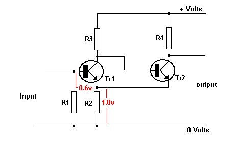
Schmitt Trigger. With no signal in,Tr1 has no forward bias and is cut off.
Learn how a Schmitt Trigger works; How to use the 555 timer as an Schmitt

Using Schmitt Trigger Circuits

The 4093 cmos integrated circuit contains four Schmitt trigger NAND gates,

If I hook the output from the schmitt trigger in circuit 1 to the trigger

performance of following 'RC-filter + Schmitt-trigger circuit':
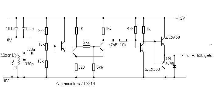
This circuit uses a Schmitt trigger to maintain an approximate square wave

than that of Schmitt-trigger circuits, because, at low input voltages,
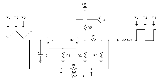
The Schmitt Trigger oscillator below employs 3 transistors, 6 resistors and
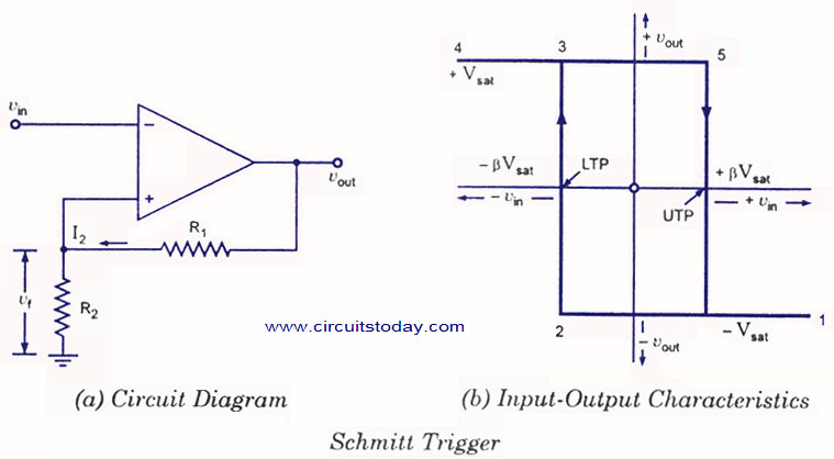
A Schmitt trigger circuit is a fast-operating voltage-level detector.
A Schmitt trigger oscillator (74C14) and MOSFET (IRF510) are used to drive
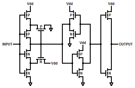
(U1) with six identical sections, each one an inverting Schmitt trigger.
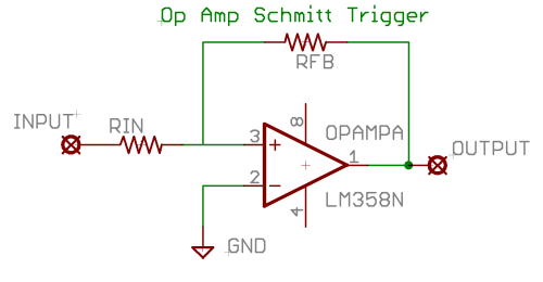
Circuit: Schmitt Trigger